2013 - 2020 fusion 1.6L Torque Specs
2013 fusion Front End Torque Specs
Click the area you are looking for!
Fusion 1.6L Repair Information
Fusion 1.6L Engine Repair Information
Here you can find information regarding the assembly of the Fusion front end. In this guide we will cover the essential repairs for the front end of this vehicle. Included within these repairs is the inner and outer tie rod removal and change, the front wheel hubs installation, ball joint removal and installation, the upper and lower control arms, and the front shock installation. Along with the repair procedures we also include the corresponding bolt torque specs for each fastener involved. These guides are intended to assist in each procedure to help diyers with the job.
Fusion Tie Rod Change/Removal
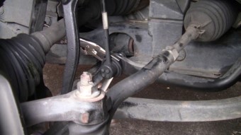
To install a new tie rod on a Fusion you must first remove the old one from the vehicle. This can be done by raising the vehicle up by either the use of a floor jack or a vehicle hoist. Once the vehicle is in the air you can remove the corresponding tire for the side that you want to change the tie rod on. Once the tire is off you can now access the old tie rod and remove it for replacement. The inner part of the tie rod uses an nut that will need to be removed, this nut may spin depending on how rusty it is. I suggest using a pair of vice grips to hold the portion of the bolt to prevent it from spinning. You may also use a wire brush to clean off the threads prior to removal and or use penatrating oil to aid in the removal. Once removed you can now tap out the tie rod from the spindle and start to remove it completely. If you want to replace just the outer portion of the tie rod you can use a wrench to hold the inner tie rod and spin off the outer tie rod. I usually count how many turns it takes to come off so that I can then use the same number when installing the new part. This helps to avoid alignment costs and hassles, although you may still want to get your vehicle realigned. Once the outer tie rod is off you can now screw on the new part and reinstall it the same way it had been removed. Once you get the nut back in place you can torque it to 35 ft-lbs. Be sure to tighten back up the nut on the middle of the tie rod to ensure it does not move your alignment. If you happen to be installing the inner tie rod as well you will need a special tool to loosen and tighten the inner part. The torque specs for the inner tie rod are 50 ft-lbs.
Outer Tie Rod35 ft-lbs
Inner Tie Rod50 ft-lbs
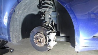
Front Wheel Hub Installation
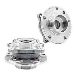
To install the new wheel hub you must first remove the old hub from the vehicle. To start off you must first jack up the vehicle and remove the lugnuts from the side of the vehicle that you want to replace the part on. Once the tire is off you will need to remove the bolts from the brake bracket on the steering knuckle. These bolts will be rather tight so you may want to use an impact or find some leverage. Once removed you can move the brake assembly out of the way and remove the brake rotor from the vehicle. Now you can move onto the center hub nut located in the center of the wheel. This nut will be very tight so I recommend using some penetration fluid and possibly an impact for removal. Once you have this nut removed you must move to the rear of the hub and remove the 4 bolts which hold the hub to the steering knuckle. This is best done by turning the steering wheel from one side to the other. With the 4 bolts removed you can remove the hub from the knuckle. The hub is typically corroded or rusted into place so this step may require some force to achieve. I recommend putting one of the bolts back into the hub a little ways and then using that bolt to hammer the hub outwards or away from the vehicle. With the hub now removed you can start to install the new hub in the reverse order. Starting with lightly tapping the hub into place and then tightening the 4 hub bolts to 98 ft-lbs. From here you can reintall the center hub nut and torque it to 148 ft-lbs. With the hub securely in place you can go ahead and reassemble the brake system by tightening the brake bracket bolts to 75 ft-lbs. From here you can reinstall the wheel and you are completed with the job.
Front Axle Nut148 ft-lbs
Front Hub Bolts98 ft-lbs
Front Brake Bracket75 ft-lbs
Lugnuts95 ft-lbs
Front Ball Joint Installation
Fusion Front Lower Ball Joint Torque Spec : 76 ft-lbs
The Fusion has one ball joint being the lower ball joint. The lower ball joint on the ford fusion is apart of the lower control arm. The lower ball joint contains a pinch bolt which is used to keep it fastened. This pinch bolt gets tightened to 76 ft-lbs.
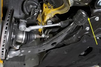
Front Control arms Installation
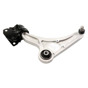
Lower Control Arm
The Ford Fusion only has one control arm being the lower control arm. The lower control arm on this vehicle uses 3 bolts to connect it to the frame of the vehicle and then a pinch bolt to connect the lower ball joint to the steering knuckle of the car. To remove the old control arm a person will need to remove all of these fasteners in order to get the old part out from the car. You may also need to remove some of the strut bolts to allow for easier mobility of the steering knuckle. When installing the new part make sure to tighten the 2 similar bolts that go from the arm to the frame to 121 ft-lbs. The leftover frame bolt gets tightened to 160 ft-lbs. Finally the lower ball joint pinch bolt should be tightened to 76 ft-lbs. If possible be sure to have the wheel and knuckle at ride height during the tightening sequence.
Lower Arm Ball Joint Bolt76 ft-lbs
Lower Arm Frame Bolt160 ft-lbs
Lower Arm Frame Bolts121 ft-lbs
Front Strut Installation
To replace the front struts on the Ford Fusion you will need to lift the vehicle up into the air and start by removing the tire on the side you want to replace. Once the tire is off the first thing to do is remove the ABS sensor bolts so that you don't put stress on the bolts or ABS sensor cord. Next you can remove the sway bar link bolt from the side of the strut. With the sway bar removed you can start to remove the lower strut bolts. There should be 2 larger bolts which are used to clamp the bottom of the strut to the steering knuckle. You may need to use a hammer to pound these bolts out once loosened. I always put the nut on a few threads before tapping it to protect the threads from damage. With the lower 2 bolts removed the last fasteners to take off are located at the top of the strut and can be accessed from under the hood. You may need to take some of the wiper area trim off of the car to allow better access to the bolts which hold the top of the strut in. There are typically 4 of them. Once removed the strut should come out from the car. The new strut can be installed in reverse order of the removal. Starting with sliding the new strut into the strut tower and tightening the upper bolts to 25 ft-lbs. Then you can install the lower strut bolts and tighten them to 70 ft-lbs. The stabilizer nut can be tightened down to 35 ft-lbs.
Front Strut Upper Bolts25 ft-lbs
Front Strut Lower Bolts70 ft-lbs
Front Stabilizer Endlink35 ft-lbs
Front Swaybar Installation
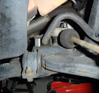
The front swaybar on the fusion consists of a series of brackets that hold it to the frame of the vehicle and a couple of endlink nuts that fasten it the the outer side of the car. To remove the swaybar you will need to jack up the front of the vehicle and remove both the endlink nuts as well as the brackets. To install the new swaybar you will need to move it back into the place as the old one and torque the endlink nuts to 35 ft-lbs and then torque the bracket bolts to 52 ft-lbs as well.
Front Swaybar Bracket52 ft-lbs
Front Swaybar Endlinks35 ft-lbs
| Front Steering Torque Specs | |
|---|---|
| Outer Tie Rod Torque Spec | 35 ft-lbs |
| Inner Tie Rod Torque Spec | 50 ft-lbs |
| Front Wheel Hub / Knuckle | |
| Brake Caliper Bracket Torque Spec | 75 ft-lbs |
| Wheel Axle Nut Torque Spec | 148 ft-lbs |
| Front Wheel Hub Bolts Torque Spec | 98 ft-lbs |
| Swaybar Mount Torque Spec | 52 ft-lbs |
| Swaybar Endlink Torque Spec | 35 ft-lbs |
| Control Arms Torque Specs | |
| Lower Ball Joint Torque Spec | 76 ft-lbs |
| Lower Arm Front Frame Bolt | 160 ft-lbs |
| Lower Arm Rear Bushing Frame Bolts | 121 ft-lbs |
| Front Strut and Extra Knuckle Torques | |
| Upper Strut Bolts Torque Spec | 25 ft-lbs |
| Lower Strut Bolts Torque Spec | 70 ft-lbs |
| Stabilizer Frame Bolt Torque Spec | 52 ft-lbs |
| Stabilizer Link Torque Spec | 35 ft-lbs |