2005 - 2012 fusion 2.5L Torque Specs
2010 fusion Front End Torque Specs
Click the area you are looking for!
Fusion 2.5L Repair Information
Fusion 2.5L Engine Repair Information
Here you can find information regarding the assembly of the Fusion front end. In this guide we will cover the essential repairs for the front end of this vehicle. Included within these repairs is the inner and outer tie rod removal and change, the front wheel hubs installation, ball joint removal and installation, the upper and lower control arms, and the front shock installation. Along with the repair procedures we also include the corresponding bolt torque specs for each fastener involved. These guides are intended to assist in each procedure to help diyers with the job.
Fusion Tie Rod Change/Removal
To install a new tie rod on a Fusion you must first remove the old one from the vehicle. This can be done by raising the vehicle up by either the use of a floor jack or a vehicle hoist. Once the vehicle is in the air you can remove the corresponding tire for the side that you want to change the tie rod on. Once the tire is off you can now access the old tie rod and remove it for replacement. The inner part of the tie rod uses an nut that will need to be removed, this nut may spin depending on how rusty it is. I suggest using a pair of vice grips to hold the portion of the bolt to prevent it from spinning. You may also use a wire brush to clean off the threads prior to removal and or use penatrating oil to aid in the removal. Once removed you can now tap out the tie rod from the spindle and start to remove it completely. If you want to replace just the outer portion of the tie rod you can use a wrench to hold the inner tie rod and spin off the outer tie rod. I usually count how many turns it takes to come off so that I can then use the same number when installing the new part. This helps to avoid alignment costs and hassles, although you may still want to get your vehicle realigned. Once the outer tie rod is off you can now screw on the new part and reinstall it the same way it had been removed. Once you get the nut back in place you can torque it to 35 ft-lbs. Be sure to tighten back up the nut on the middle of the tie rod to ensure it does not move your alignment. If you happen to be installing the inner tie rod as well you will need a special tool to loosen and tighten the inner part. The torque specs for the inner tie rod are 76 ft-lbs.
Outer Tie Rod35 ft-lbs
Inner Tie Rod76 ft-lbs
Front Wheel Hub Installation
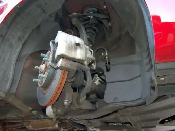
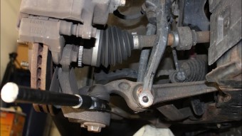
To install the new wheel hub you must first remove the old hub from the vehicle. On this car the hub and bearing is actually apart of the entire steering knuckle. This means that if you want to replace the bearing you will need to remove the knuckle itself. To start off you must first jack up the vehicle and remove the lugnuts from the side of the vehicle that you want to replace the part on. Once the tire is off you will need to remove the bolts from the brake bracket on the steering knuckle. These bolts will be rather tight so you may want to use an impact or find some leverage. Once removed you can move the brake assembly out of the way and move the brake rotor from the vehicle. Now you have access to all the connecting points of the steering knuckle, these include the lower ball joint, strut, and tie rod end. Before removing the connecting points make sure to remove the axle nut from the center of the hub. I recommend using an impact and some penetrating oil in order to loosen the nut. Once the nut is removed make sure the axle moves freely and then move onto the other components. Starting with the lower ball joint there is a pinch bolt that will need to be removed in order to lower the control arm from the knuckle. The tie rod merely needs to be loosened and removed while the strut will need to be loosened and hammered out. With everything removed the knuckle should just come out of the vehicle. From this point you can either install an entirely new steering knuckle with the bearing already in place, or press the old bearing out of the knuckle and press in a new bearing. Whichever way you choose the next step is to install the knuckle back into the vehicle using the reverse procedure as when it was removed. The upper ball joint should be tightened to 35 ft-lbs, the tie rod to 35 ft-lbs, and the lower ball joint nuts to 148 ft-lbs. The center axle nut will need to be tightened to 180 ft-lbs. With everything put back together you can reinstall the brake system and the wheel and tighten the lugnuts to 95 ft-lbs.
Front Axle Nut180 ft-lbs
Lugnuts95 ft-lbs
Front Ball Joints Installation
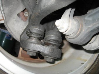
The Fusion has two sets of front ball joints being the upper and lower ball joints. The most common one for replacement is the lower ball joint which is apart of the lower control arm. On this specific model there is 2 lower ball joints right next to each other which get tightened down to 148 ft-lbs. As for the upper ball joint it comes out of the upper control arm and the nut which holds them together should be tightened down to 35 ft-lbs.
Front Upper Ball Joint35 ft-lbs
Front Lower Ball Joint148 ft-lbs
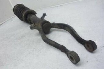
Front Control arms Installation
Lower Control Arm
On the ford Fusion there is 2 control arms one being the upper and one being the lower. The upper control arm can be replaced by first removing it from the steering knuckle and the frame. There is one nut on the control arms ball joint which tightens it to the steering knuckle and 2 bolts that tightened it to the frame. Once those fasteners are removed you can replace the part with a new one. To install the new part you will have to torque down the 2 frame bolts to 85 ft-lbs and the ball joint nut to 35 ft-lbs. As for the lower control arm you will have to remove 2 nuts from the 2 ball joints which connect to the steering knuckle. Next there is a single frame bolt that tightens the lower control arm to the frame. Once the fasteners are removed you can remove the part and begin to tighten up the new part into the vehicle. The ball joints will need to be tightened down to 148 ft-lbs and the frame bolts to 81 ft-lbs plus an additional 90 degree turn.
Lower Arm Ball Joint Nuts148 ft-lbs
Lower Arm Frame Bolt81 ft-lbs + 90°
Upper Arm Frame Bolts85 ft-lbs
Upper Arm Ball Joint35 ft-lbs
Front Strut Installation
To replace the front struts on the Ford Fusion you will need to lift the vehicle up into the air and start by removing the tire on the side you want to replace. Once the tire is off the first thing to do is remove the ABS sensor bolts so that you don't put stress on the bolts or ABS sensor cord. Next you can remove the sway bar link from the top of the wishbone or the backwards V shaped part that connects to the strut. Once removed you can then remove the wishbone from the struts bottom and then the bottom bolt of the wishbone that connect to the lower control arms. The wishbone can now be removed by sliding it down from the strut, you may have to hammer on it some. Next you can remove the upper strut nuts that are located underneath the hood. There are 3 nuts in total that can be loosened and removed. From this point you can grab the strut and remove it from the vehicle and then put the new part back in place and install in reverse order. The upper strut nuts get tightened to 29 ft-lbs. The bottom wishbone bolt gets tightened to 76 ft-lbs, the upper wishbone to 38 ft-lbs, the swaybar endlink to 40 ft-lbs.
Front Strut Upper Nuts29 ft-lbs
Front Strut Lower Bolt38 ft-lbs
Front Wishbone Bolt76 ft-lbs
Front Stabilizer Endlink40 ft-lbs
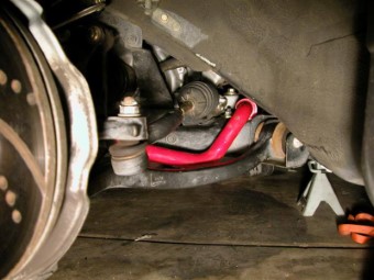
Front Swaybar Installation
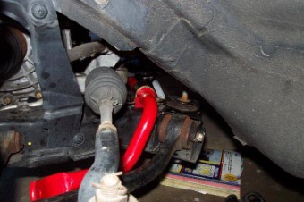
The front swaybar on the fusion consists of a series of brackets that hold it to the frame of the vehicle and a couple of endlink nuts that fasten it the the outer side of the car. To remove the swaybar you will need to jack up the front of the vehicle and remove both the endlink nuts as well as the brackets. To install the new swaybar you will need to move it back into the place as the old one and torque the endlink nuts to 40 ft-lbs and then torque the bracket bolts to 52 ft-lbs as well.
Front Swaybar Bracket52 ft-lbs
Front Swaybar Endlinks40 ft-lbs
| Front Steering Torque Specs | |
|---|---|
| Outer Tie Rod Torque Spec | 37 ft-lbs |
| Inner Tie Rod Torque Spec | 50 ft-lbs |
| Front Wheel Hub / Knuckle | |
| Brake Caliper Bracket Torque Spec | 80 ft-lbs |
| Wheel Axle Nut Torque Spec | 180 ft-lbs |
| Swaybar Mount Torque Spec | 52 ft-lbs |
| Swaybar Endlink Torque Spec | 37 ft-lbs |
| Control Arms Torque Specs | |
| Lower Ball Joint Torque Spec | 37 ft-lbs |
| Lower Arm Front Frame Bolt | 85 ft-lbs |
| Lower Arm Rear Bushing Frame Bolts | 85 ft-lbs |
| Front Strut and Extra Knuckle Torques | |
| Upper Strut Nuts Torque Spec | 27 ft-lbs |
| Lower Strut Bolt Torque Spec | 65 ft-lbs |
| Stabilizer Frame Bolt Torque Spec | 52 ft-lbs |
| Stabilizer Link Torque Spec | 37 ft-lbs |