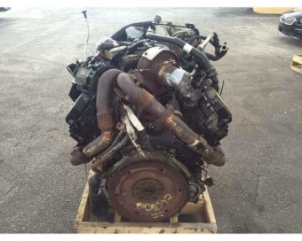
Here you can find information regarding the assembly of the Ford 6.0L Modular engine. In this guide we will
start from the inside of the engine including the
crankshaft, connecting rods, and piston ring installation and then move outwards all the way to the pulley belt
system. Along the way correct procedures and torque specs
will be given to aid in the assembly of the engine. Feel free to start from the beggining and work your way
outwards or skip ahead to your current position in the engine for what you may need.
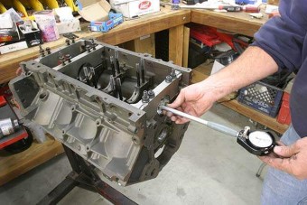
Crankshaft Main Caps Installation
The Ford 6.0L block uses standard main caps that have 2 long bolts and 2 normal bolts per each cap. The main caps should all be installed and finger tightened with oil before torqueing.
Once all the caps are installed and slightly tightened you can start from the middle cap and torque the 4 bolts to 76 ft-lbs. Once the middle one is torqued to 76 you can move outwards going from side to
side torqueing to the same value. Once all cap bolts have been tightened to 76 ft-lbs you can start the process over but this time going up to 96 ft-lbs. Once done be sure to turn over the crank to ensure
that it rotates smoothly and isn't bound up by anything.
Ford Excursion Main Cap Torque Specs : 120 ft-lbs | 170 ft-lbs | 190 ft-lbs
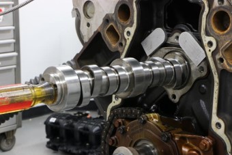
Camshaft Installation
The Ford 6.0L uses a OHV pushrod system that includes the camshaft being located in the middle of the engine. Before installing the camshaft be sure to check the cam bearings for wear
and replace accordinly. To see more on how to replace camshaft bearings check out this detailed page. If all the bearings are good or replaced you can then slowly insert the camshaft into the engine
going from the front to the back. With the camshaft in align the camshaft gear with the crank gear markings. There are 2 thrust plate bolts that hold the camshaft from coming out. These bolts
should be torqued to 23 ft-lbs.
Ford Excursion Camshaft Thrust Bolts Torque: 23 ft-lbs
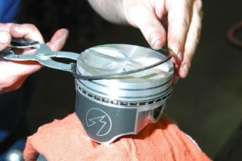
Piston and Connecting Rod Installation
To install the pistons and connecting rods you must first install the piston rings into each piston. Be careful
not to stretch the rings or break them during installation. Make sure to put the correct rings in the correct
positions, this can be determined by looking at
the instructions given with the new rings. Each ring manufacturer is different so be sure to check for your
specific rings. Once the rings have been installed you can now fit the connecting rod bearings into the end caps
and lube them up with oil or lithium grease. The piston can now be lowered into the cylinder, make sure the dot
or mark is facing the front of the engine and that you don't scratch the cylinder.
Once installed you can match the connecting rod caps with the correct rods and start to torque the connecting
rod bolts to 33 ft-lbs during the first stage and then to 50 ft-lbs for the second stage. After all are done rotate the crank
to ensure all pistons move smoothly in and out of their cylinders.
Ford Excursion Connecting Rod Torque Specs : 33 ft-lbs | 50 ft-lbs
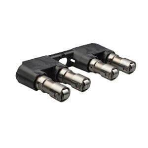
Lifter Installation
The Ford 6.0L has 32 valves which are controlled by a series of lifters that push up on pushrods and rocker arms. These lifters are installed into the engine block before
the cylinder head gets installed and should be soaked in engine oil prior to installation. They can be dropped into place and then aligned with the lifter guides. The guides
should be installed evenly and then tightened down to ensure the lifters do not fall out when installing the cylinder head and pushrods.
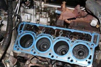
Cylinder Head Installation
The first thing you must do when installing cylinder heads is to ensure both the block and head surfaces are
completely clean from dust, oil, and any debris. The next thing you must do is set the pistons to their correct
locations, typically this means putting the #1 piston to TDC or Top Dead Center. Once everything is ready you
can install the head gasket onto the engine block by using the alignment pins to place it properly.
Something I usually do is spray down the head gasket with some engine copper spray from permatex which you can
find here, this ensures that any gaps that could be present between the 2 surfaces gets filled with the
spray. It
also helps to transfer heat between the 2 metals. With the gasket now in place you can set the cylinder head onto
the gasket and block, if needed have someone assist with this process as the head can be heavy
and you don't want to scratch anything or drop it! Once the head has been placed you will want to start
installing the head bolts to make sure it doesn't move. Be sure to buy new head bolts as many manufacturers
use TTY or Torque to Yield head bolts meaning they stretch during torqueing and cannot be used twice. Also make
sure to lubricate the bolts in clean engine oil before installing them into the head.
Once all the head bolts have been installed and finger tightened you can start the torqueing process, almost all
head bolts have a multi-step process for torqueing. The 6.0L has a 3 stage process and starts off with 65 ft-lbs and
then moves to 85 ft-lbs and finally 95 ft-lbs. Be sure to follow the proper order for tighteneing the bolts and that you hit each bolt during each stage.
The order the bolts need to be tightened starts from the inside 2 and slowly moves outwards from there going in a cross pattern.
Ford Excursion Cylinder Head Torque Specs : 65 ft-lbs | 85 ft-lbs | 95 ft-lbs
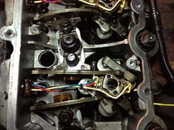
Pushrod and Rocker Arms Installation
With the cylinder head torqued down into place you can begin to install the pushrods and rocker arms into the engine. The pushrods just slide into place with the copper end on the top, be sure they
fall properly into the lifters down below. With the pushrods in place you can put the rocker arms onto them and the top of the valves. The rocker arms are fastened down with bolts that should be torqued to
20 ft-lbs. Be sure that the engine is at TDC before tightening down the rocker arm bolts to prevent valve damage.
Ford Excursion Rocker Arm Torque Spec: 20 ft-lbs
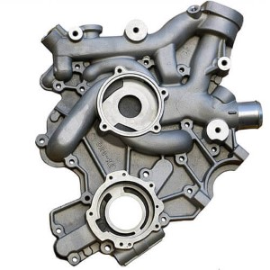
Timing Cover Installation
The timing cover on the 6.0L is rather simple but is a very important component that keeps the oil inside the
engine rather than leaking out onto the ground. For this reason I recommend using a new
gasket along with some silicone sealant to ensure the cover does it's job. Another important thing about the
timing cover is that it holds the crankshaft seal into place. Be sure to check out your seal
for any defects and or cracks. If your seal looks to be in good condition then you can reuse it without a
problem as long as you coat it with some clean engine oil before installing the cover. To prepare
the cover for installation you should clean both the cover's surface as well as the engine blocks surface. Next
you can install the new gasket onto the cover and follow it up with some silicone sealant.
I always use permatex's ultra black silicone sealant as it has an advance formula to resist engine oil. Once the
gasket and silicone has been placed onto the cover you can carefully place it onto the block
and start to install the cover bolts. If you used sealant be sure to follow the instructions included with the
product for the best results! The front cover bolts should be torqued to 18 ft-lbs.
Ford Excursion Timing Cover Torque Specs : 18 ft-lbs
Oil Pump Installation
When installing the oil pump be sure to use the proper sealant around the pump base to ensure that oil pressure
doesn't drop due to leakage. After preparing the contact surfaces carefully
install the oil pump gear and dampener onto the crankshaft. Once the dampener is on you can install the oil pump housing cover with a new gasket and some silicon. These bolts
can be torqued to 8 ft-lbs. The pickup tube can now be installed onto the lower pump and torqued to 10 ft-lbs.
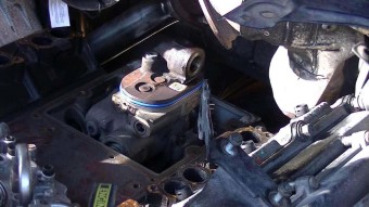
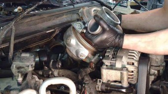
With the pickup tube installed the last part of the oil pump is the high pressure part on the upper end of the engine.
The high pressure oil pump is located on the top of the engine between both cylinder heads. It has a cover which protects it from debri and keeps oil inside of the engine.
To replace the old pump you will need to unbolt the cover bolts and then unbolt the pump torx bolts. Once the bolts are removed the pump should lift straight out of the engine.
Be careful not to lose the o-ring on the bottom of the pump down into the engine. Your new pump should have a new one included with it. Before installing the new pump clean
up both the engine surface and the new pumps surface and then place the new o ring in place and lower the new pump into the engine. From here you can install the pump mounting
bolts and tighten them to 18 ft-lbs. With the pump tightened down you can then put the cover back in place using a new gasket or the old gasket and some silicon sealant.
The cover bolts should be tightened to 8 ft-lbs. Finally the discharge tube on the top of the high pressure pump should be tightened to 8 ft-lbs.
Ford Excursion Oil Pump Housing Torque Specs : 8 ft-lbs
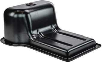
Much like the timing cover on the 6.0L the oil pan plays an important role in keeping the engine oil inside the
engine. For this reason I recommend using a new gasket as well as some silicone sealant
during installation. Using the same technique as before with the cover you clean the surfaces of both the oil
pan and the engine block and then install the new gasket onto the block and then follow
it up with some silicone sealant. Be sure to follow your sealants instructions to ensure you get the best seal
from your application. The oil pan bolts torque to 10 ft-lbs in a cross
pattern design regardless if they are the upper or lower set of bolts.
Along with the pan is the oil pan drain plug, this gets removed and reinstalled quite frequently and can be
torqued down to 32 ft-lbs.
Ford Excursion Lower Oil Pan Bolts Torque Specs : 10 ft-lbs
Ford Excursion Upper Oil Pan Bolts Torque Specs : 10 ft-lbs
Ford Excursion Oil Drain Plug Torque Specs : 32 ft-lbs
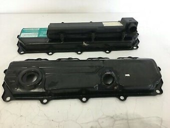
Valve Covers Installation
The valve cover installation is rather simple, there are rubber seals for each bolt hole and a silicone gasket
that prevents oil from leaking out of the engine. It is recommended to replace both the seals
and the gaskets although if they are in good condition you can reuse them. If you do choose to reuse them I
would use some silicone sealant along with the silicone gasket to ensure it does not leak.
The valve cover bolts torque down to 106 in-lbs or about 9 ft-lbs in a criss cross order. Be sure not to miss
any bolts to avoid having oil leak out onto the exhaust pipes and cause a lot of smoking.
Ford Excursion Valve Cover Torque Specs : 9 ft-lbs
Intake Manifold and Turbocharger Installation
When installing the intake manifold you want to make sure you have all the surfaces as well as intake holes
cleaned out before placing the manifold into position. Once cleaned you can then place
the intake manifold gaskets onto the alignment pins. If you want you can also use a little bit of sealant on the
gaskets to help ensure there are no leaks. With the gaskets in place you can now put
the manifold down onto the gaskets and begin to install the bolts. The intake manifold plenum bolts torque to 8 ft-lbs
and can be tightened starting from the inside and going outwards.
With the intake installed we can now move to the turbocharger, starting with the exhaust inlet pipes. These pipes come from the
exhaust manifold and bolt directly to the turbocharger on top of the engine. To start with the turbocharger installation we can
bolt down the turbo to the top of the engine using the turbocharger mounting bolts. These bolts will need to be torqued down to 28 ft-lbs.
Next we can take the two exhaust pipes that come from the exhaust manifolds and tighten them up to the back of the turbocharger using the supplied clamps
and tightening the bolts to 9 ft-lbs. We then can tighten up the turbo flange to the exhaust/EGR tube and the turbo's oil supply tube using 20 ft-lbs. Finally we have
the turbo to the intake manifold connection and the turbochargers down exhaust pipe which ends up going to the rear of the vehicle. The intake connection or the pedestal bolts
can be tightened to 23 ft-lbs and the exhaust down pipe can be tightened to 30 ft-lbs.
Ford Excursion Intake Manifold Plenum Torque Specs : 8 ft-lbs
Ford Excursion Turbocharger Mounting Bolts Torque Spec : 28 ft-lbs
Ford Excursion Turbo Pedestal Bolts Torque Specs : 23 ft-lbs
Ford Excursion Turbo Exhaust Down Pipe Torque Spec : 30 ft-lbs
Exhaust Manifold Installation
The exhaust manifold can be installed by cleaning the surface areas on both the head an the manifold itself and
then by using the exhaust manifold gasket and putting it in place. Once the gasket is in
location you can put the manifold onto the heads and begin to torque the bolts to 28 ft-lbs. I always use some
copper spray from permatex on the exhaust manifold gaskets to ensure I do not end up with
any exhaust leaks once done. The exhaust system also consists of a back pressure tube which includes the assembly bolts
as well as a sensor. The assembly bolts should be tightened to 22 ft-lbs while the sensor and its mount can be tightened to 8 ft-lbs.
Ford Excursion Exhaust Manifold Torque Specs : 28 ft-lbs
Ford Excursion Exhaust Back Pressure Mount Torque Specs : 22 ft-lbs
Ford Excursion Exhaust Back Pressure Sensor Torque Specs : 8 ft-lbs
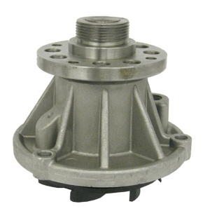
Water Pump and Thermostat Installation
The water pump can be installed by using a new gasket and if desired some silicone sealant to aid it. Once
prepared the pump can be moved into placed and the bolts should be torqued to 18 ft-lbs.
The water pump pulley can be torqued to the water pump itself with 23 ft-lbs as well.
Ford Excursion Water Pump Torque Specs : 18 ft-lbs
Ford Excursion Water Pump Pulley Torque Specs : 23 ft-lbs
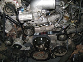
Front Dress and Pulley belt Installation
Most of what is left on the engine is just place and tighten objects such as the belt pulleys, belt tensioner,
crankshaft pulley, and motor mounts. If the items have a gasket and hold either
oil or coolant inside the engine then feel free to add some sealant along with the gasket. Always be sure to
inspect your gaskets and replace them if there is any deteriation or flaws with them. For the
belt system the crank shaft pulley alternators get torqued to 35 ft-lbs. The belt
tensioner can be torqued to 18 ft-lbs and the idler pulley can both be torqued down to 35 ft-lbs. When installing be sure they
both turn smoothly and if they do not then replace them with new ones as the bearings can go bad.
As for the motor mounts there is a series of nuts which are used to tighten down the engine to the vehicle frame. These nuts should be
tightened down to 83 ft-lbs in order for them to stay tight through the engine and road vibrations. The alternator mounts can be
tightened down to 35 ft-lbs and the power steering pump bolts can be tightened to 18 ft-lbs.
Ford Excursion Crankshaft Pulley Torque Specs : 35 ft-lbs
Ford Excursion Idler Pulley Torque Specs : 35 ft-lbs
Ford Excursion Belt Tensioner Torque Specs : 18 ft-lbs
Ford Excursion Motor Mount Nuts Torque Spec : 83 ft-lbs
Ford Excursion Crossmember to Frame Torque Specs : 66 ft-lbs
Ford Excursion Alternator Mounts Torque Spec : 35 ft-lbs
Ford Excursion Power Steering Pump Torque Specs : 18 ft-lbs
 The Ford 6.0L has 32 valves which are controlled by a series of lifters that push up on pushrods and rocker arms. These lifters are installed into the engine block before
the cylinder head gets installed and should be soaked in engine oil prior to installation. They can be dropped into place and then aligned with the lifter guides. The guides
should be installed evenly and then tightened down to ensure the lifters do not fall out when installing the cylinder head and pushrods.
The Ford 6.0L has 32 valves which are controlled by a series of lifters that push up on pushrods and rocker arms. These lifters are installed into the engine block before
the cylinder head gets installed and should be soaked in engine oil prior to installation. They can be dropped into place and then aligned with the lifter guides. The guides
should be installed evenly and then tightened down to ensure the lifters do not fall out when installing the cylinder head and pushrods.
 With the cylinder head torqued down into place you can begin to install the pushrods and rocker arms into the engine. The pushrods just slide into place with the copper end on the top, be sure they
fall properly into the lifters down below. With the pushrods in place you can put the rocker arms onto them and the top of the valves. The rocker arms are fastened down with bolts that should be torqued to
20 ft-lbs. Be sure that the engine is at TDC before tightening down the rocker arm bolts to prevent valve damage.
With the cylinder head torqued down into place you can begin to install the pushrods and rocker arms into the engine. The pushrods just slide into place with the copper end on the top, be sure they
fall properly into the lifters down below. With the pushrods in place you can put the rocker arms onto them and the top of the valves. The rocker arms are fastened down with bolts that should be torqued to
20 ft-lbs. Be sure that the engine is at TDC before tightening down the rocker arm bolts to prevent valve damage.