1997 - 2002 Expedition 5.4L Torque Specs
2000 Expedition Front End Torque Specs
Click the area you are looking for!
Expedition 4.6L Repair Information
Expedition 4.6L Engine Repair Information
Here you can find information regarding the assembly of the Expedition front end. In this guide we will cover the essential repairs for the front end of this vehicle. Included within these repairs is the inner and outer tie rod removal and change, the front wheel hubs installation, ball joint removal and installation, the upper and lower control arms, and the front shock installation. Along with the repair procedures we also include the corresponding bolt torque specs for each fastener involved. These guides are intended to assist in each procedure to help diyers with the job.
Expedition Tie Rod Change/Removal
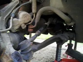
To install a new tie rod on a Expedition you must first remove the old one from the vehicle. This can be done by raising the vehicle up by either the use of a floor jack or a vehicle hoist. Once the vehicle is in the air you can remove the corresponding tire for the side that you want to change the tie rod on. Once the tire is off you can now access the old tie rod and remove it for replacement. The inner part of the tie rod uses a 13/16 nut that will need to be removed along with a cotter pin holding the nut from spinning, this nut may spin along with the tie rod joint depending on how rusty it is. I suggest using a pair of vice grips to hold the portion of the bolt to prevent it from spinning. You may also use a wire brush to clean off the threads prior to removal and or use penatrating oil to aid in the removal. Once removed you can now tap out the tie rod from the spindle and start to remove it completely. If you want to replace just the outer portion of the tie rod you can use a wrench to hold the inner tie rod and spin off the outer tie rod. I usually count how many turns it takes to come off so that I can then use the same number when installing the new part. This helps to avoid alignment costs and hassles, although you may still want to get your vehicle realigned. Once the outer tie rod is off you can now screw on the new part and reinstall it the same way it had been removed. Once you get the 13/16 nut back in place you can torque it to 65 ft-lbs. Be sure to tighten back up the nut on the middle of the tie rod to ensure it does not move your alignment. If you happen to be installing the inner tie rod as well you will need a special tool to loosen and tighten the inner part. The torque specs for the inner tie rod are 65 ft-lbs.
Outer Tie Rod65 ft-lbs
Inner Tie Rod65 ft-lbs
2WD/RWD Front Wheel Hub Installation
To install the new wheel hub you must first remove the old hub from the vehicle. To do this you must first jack up the vehicle and remove the lugnuts from the side of the vehicle that you want to replace the part on. Once the tire is off you will need to remove the bolts from the brake bracket on the steering knuckle. These bolts will be rather tight so you may want to use an impact or find some leverage. Once removed you can move the brake assembly out of the way to allow room for the rotor to be removed. The next step is to remove the center 27mm nut that holds the hub bearing and brake rotor into place. This nut can be accessed by removing its cover and then uninstalling the cotter pin holding the nut from spinning. An impact is nice during this part as the nut is very tight. Once removed you can then remove the hub and brake rotor from the vehicle as one assembly. The wheel bearings may fall out as this gets removed, when reinstalling be sure to use new bearings and to pack them with grease before installing. The bearings get installed according to their outer race placements. For instance the inside bearing should taper inwards and the outer should taper inwards as shown in the picture. Once the hub has been reinstalled with the bearings properly placed you can tighten the 27mm nut down to 12 ft-lbs. Once tightened you can torque the nut to 30 ft-lbs while spinning the rotor at the same time, this procedure is to set the bearings. Next you will need to loosen the nut a quarter turn and then tighten it down by hand. The castle nut and cotter pin can now be installed and the dust cover replaced. Now that the brake rotor is installed again you can reinstall the brake system by pushing the brake caliper back onto the rotor. Once in place the brake bracket bolts can be torqued down to 145 ft-lbs and if removed the caliper slide bolts can be torqued to 25 ft-lbs. With the brake assembly reinstalled you can now install the wheel back onto the vehicle and torque the lugnuts down to 125 ft-lbs.
2WD Front Wheel Hub30 ft-lbs | loosen | hand tight
Front Brake Bracket145 ft-lbs
Front Caliper Slide Bolts25 ft-lbs
Lugnuts125 ft-lbs
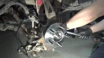
4WD Front Wheel Hub Installation
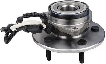
To install the new wheel hub you must first remove the old hub from the vehicle. To do this you must first jack up the vehicle and remove the lugnuts from the side of the vehicle that you want to replace the part on. Once the tire is off you will need to remove the bolts from the brake bracket on the steering knuckle. These bolts will be rather tight so you may want to use an impact or find some leverage. Once removed you can move the brake assembly out of the way to allow room for the rotor to be removed. With the brake assembly off the rotor can now be taken off of the vehicles hub and placed aside. The next stage is to remove the hub itself from the vehicle, to start with we need to remove the axle nut by removing the cotter pin and castle nut retaining it in. The nut itself is 35mm and is very tight, I recommend spraying some penetration oil onto the nut before attempting removal of the nut and if available use an impact to make the job faster. With the nut removed we now have to remove the bolts on the rear side of the hub. These bolts hold the actual hub onto the steering knuckle and are also tight. An easy way to access these bolts is to turn the steering wheel to allow more access at them. There are 3 of them and their size is 15mm, once all are removed you can then push the axle through the hub and pound the hub off of the vehicle. Depending on how old the hub is there may be more or less corrosion holding it in place. Be careful when pounding or prying it off as you don't want to damage anything needed on the vehicle. If your vehicle has an abs sensor be sure to unplug it before pulling the hub away from the vehicle. With the old hub off we can clean up the hub area and then install the new hub onto the vehicle. The new hub can be lightly pressed into the place of the old one and then tightened down by the same 3 bolts. These bolts torque to 150 ft-lbs. Once all 3 bolts are installed you can then reinstall the center wheel nut with some loctite and hand tighten it down for now. Next the brakes need to be reassembled starting with putting the brake rotor back into place and then installing the brake bracket back onto the vehicle. The bracket can be torque down to 145 ft-lbs, if the caliper was removed the caliper slide bolts can be torqued to 25 ft-lbs. Now we can move back to the center axle nut and torque it down to 225 ft-lbs, you may need someone to hold down the brake inside the vehicle in order to prevent the rotor from turning. Another method is to use a screwdriver and insert it into the rotors grooves. Once the nut is torqued properly you can reinstall the castle cover and cotter pin. The wheel can then be installed onto the vehicle and the lugnuts torqued to 125 ft-lbs.
Front Wheel Axle Nut225 ft-lbs
Front Wheel Hub150 ft-lbs
Front Brake Bracket145 ft-lbs
Front Caliper Slide Bolts25 ft-lbs
Lugnuts125 ft-lbs
Front Ball Joints Installation
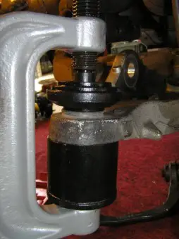
The Expedition has two sets of front ball joints being the upper and lower ball joints. The most common one for replacement is the lower ball joint which is apart of the lower control arm. Although it is apart of the control arm it can be pressed out and a new one can be pressed in. This is a pretty involving job which includes several tools that may not be available to the average person. These include a ball joint press, 2 jacks or a hoist and a jack, and typically an impact or large breaker bar for the larger bolts and nuts. To start with the job you will need to remove the wheel from the vehicle and disassemble the brake system so that the rotor can be taken off. With the brake rotor off you now can remove the center axle nut and lower ball joint nut. Before removing the ball joint nut you should have a jack underneath the lower control arm to support the torsion and aid in disassembly. This should not be holding the vehicle up! Another jack or a car hoist should be used to support the vehicle, this jack is just to keep the lower arm in place and to use for up and down movement. With the lower ball joint nut off and the axle nut removed you can move the steering knuckle away from the vehicle and then access the ball joint more directly. Here is where you will need the ball joint press to press the joint out of the lower control arm. The same press can also be used to press a new joint in. with the new ball joint in place you can then put the axle back into the knuckle while also realigning the ball joint into the knuckle. The lower ball joint nut can be torqued down to 100 ft-lbs. And then the axle nut can be torqued to 225 ft-lbs. With the axle and lower control arm back in place you can reassemble the braking system and reinstall the wheel. Most of this is explained in other sections of this page and can be followed based on them.
Front Lower Ball Joint100 ft-lbs
Front Upper Ball Joint65 ft-lbs
Front Control arms Installation
Lower Control Arm
The front control arms consist of two portions per side, these are the upper and lower control arms. I'm going to start from the lower control arm and then move to the upper one. There are two main fasteners that hold in the lower control arm. They are both located in the rear part of the control arm and are fastened to the frame by a series of bolts and nuts. There is also the ball joint nut towards the outer part of the vehicle which will need to be removed in order to uninstall the control arm. During assembly the rear bolts/nuts can be torqued to 225 ft-lbs. The ball joint nut can be torqued to 100 ft-lbs.
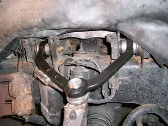
Upper Control Arm
The next control arm is refered to the upper control arm. The role of this part is to hold the spindle and wheel assembly aligned properly. Much like the lower control arm this part consists of 3 fasteners, two being bolts in the back of the part and one being a ball joint in the front or closest area of the part. The two bolts in the back will need to be torqued to 110 ft-lbs. The last fastener is the nut that holds the upper ball joint onto the spindle. This nut will also need to be torqued to 65 ft-lbs. All bolts can be installed with some blue loctite to ensure that none of them come loose while driving the vehicle.
Lower Arm Bolt and Nut225 ft-lbs
Lower Arm Ball Joint Nut100 ft-lbs
Upper Arm Bolt and Nut110 ft-lbs
Upper Arm Ball Joint Nut65 ft-lbs
Front Shock Absorber installation
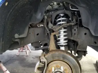
To replace the front shocks on an Expedition you will first need to remove the nuts on the top of the shock. This can be accessed from under the hood of the vehicle or by the side with a wrench. The next bolt to remove is the lower bolt that runs through the lower control arm. Once removed the shock can then be removed from the vehicle. The new shock can then be moved back into the vehicle the same way the old one came out. Once the new shock is installed you can then start installing the bolts and nuts. The upper nut can be installed the same way that it had been removed and should be torqued to 40 ft-lbs. The lower bolt may need to be aligned and pounded back into place. If you must hammer on the bolt be sure not to ruin the threads, once the bolt is through it can be torqued to 25 ft-lbs if the vehicle is 2WD or 75 ft-lbs if 4WD.
Front Shock Upper Nut40 ft-lbs
Expedition Front Shock Lower Bolt Torque Spec (2WD): 25 ft-lbs
Expedition Front Shock Lower Bolt Torque Spec (4WD): 75 ft-lbs
Front swaybar Installation
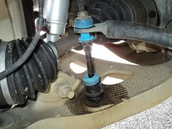
The front swaybar on the Expedition consists of a series of brackets that hold it to the frame of the vehicle and a couple of endlink nuts that fasten it the the outer side of the car. To remove the swaybar you will need to jack up the front of the vehicle and remove both the endlink nuts as well as the brackets. To install the new swaybar you will need to move it back into the place as the old one and torque the endlink nuts to 20 ft-lbs and then torque the bracket bolts to 20 ft-lbs as well.
Front Swaybar Bracket20 ft-lbs
Front Swaybar Endlinks20 ft-lbs
Steering Gear Installation
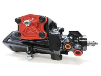
The steering gear box on the Expedition is fastened by a series of bolts that should be torqued down to 65 ft-lbs. The steering wheel bolt is tightened to 30 ft-lbs, and the pinch bolt for the intermediate shaft going between the wheel and the gear box can be torqued to 35 ft-lbs. On this vehicle there is also an idler arm that consists of center link ballstuds and brackets. The bracket bolts can be torqued to 155 ft-lbs and the ballstuds to 70 ft-lbs.
Steering Gear Bolts65 ft-lbs
Steering Wheel Bolt30 ft-lbs
Intermediate Shaft Pinch Bolt35 ft-lbs
Idler Arm Bracket Bolts155 ft-lbs
Center Link Ball Stud70 ft-lbs
| Front Steering Torque Specs | |
|---|---|
| Outer Tie Rod Torque Spec | 65 ft-lbs |
| Inner Tie Rod Torque Spec | 65 ft-lbs |
| Steering Box Bolts Torque Specs | 65 ft-lbs |
| Steering Wheel Bolt Torque Spec | 30 ft-lbs |
| Intermediate Pinch Bolt Torque Specs | 35 ft-lbs |
| Idler Arm Bracket Bolts Torque Spec | 155 ft-lbs |
| Idler Arm Ballstuds Torque Specs | 70 ft-lbs |
| Front Wheel Hub / Knuckle (2WD) | |
| Front Wheel Hub Nut Torque Specs | 30 ft-lbs | loosen | hand tight |
| Brake Caliper Bracket Torque Spec | 145 ft-lbs |
| Brake Caliper Slide Pin Torque Spec | 25 ft-lbs |
| Lugnuts Torque Spec | 125 ft-lbs |
| Front Wheel Hub / Knuckle (4WD) | |
| Front Wheel Axle Nut Torque Specs | 225 ft-lbs |
| Front Wheel Hub Bolts Torque Specs | 150 ft-lbs |
| Brake Caliper Bracket Torque Spec | 145 ft-lbs |
| Brake Caliper Slide Pin Torque Spec | 25 ft-lbs |
| Lugnuts Torque Spec | 125 ft-lbs |
| Control Arms Torque Specs | |
| Lower Ball Joint Torque Spec | 100 ft-lbs |
| Upper Ball Joint Torque Spec | 65 ft-lbs |
| Lower Arm to Frame Bolts Torque Spec | 225 ft-lbs |
| Upper Arm to Frame Bolts Torque Spec | 110 ft-lbs |
| Front Shock and Extra Knuckle Torques | |
| Upper Shock Bolt Torque Spec | 40 ft-lbs |
| Lower Shock Bolt Torque Spec (2WD) | 25 ft-lbs |
| Lower Shock Bolt Torque Spec (4WD) | 75 ft-lbs |
| Swaybar Bracket Bolts Torque Spec | 20 ft-lbs |
| Swaybar Endlinks Torque Spec | 20 ft-lbs |